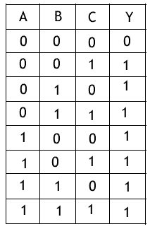
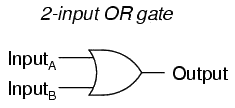
The OR gate is a basic digital logic gate. The logical operation OR is interpreted to mean that output Y=1 if inputs A=1 and B=0 or if A=0 and B=1 or both A=1 and B=1; otherwise Y=0. It has N inputs (N>=2) and one output.
| Inputs | Output | ||
|---|---|---|---|
| A | B | Y | |
| 0 | 0 | 0 | |
| 0 | 1 | 1 | |
| 1 | 0 | 1 | |
| 1 | 1 | 1 | |
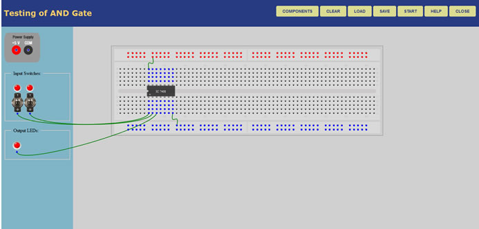
We used the following components for this experiment-
After Starting the experiment first click on the Components button to get component list. Now you can Drag and Drop any component in the circuit designing area. To make connection between components, just click on the Blue bubble of any components and Drag it to another Blue bubble of the same or any other components. To delete connection or to remove any component use Double click on that component or connection.
Connect the Vcc and Ground pins of the ICs with the power supply. Now connect the input pins of the ICs with the Input Switches. Connect the output pins with output LEDs. Only pins with Blue bubbles can be used.
Green LEDs are used for indicating logic 0 and Red LEDs are used for logic 1.
After connecting all the required components, click on the Start button.
Q: Draw a 3 input OR gate using 2 input OR gate Label the input A,B and C and output X. Write boolian expression for 3 input OR gate with truth table.
Ans: Logic digram of 3 input OR gate, using two input OR gate.
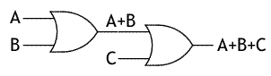
Output Y=A+B+C
Truth table: