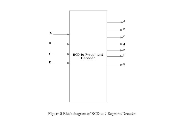
The purpose of this experiment is to design and implement combinatorial logic that will decode a 4-bit BCD input to a seven segment LED display.
Binary Coded Decimal (BCD or “8421” BCD) numbers are made up using just 4 data bits (a nibble or half a byte) similar to the Hexadecimal numbers we saw in the binary tutorial, but unlike hexadecimal numbers that range in full from 0 through to F, BCD numbers only range from 0 to 9, with the binary number patterns of 1010 through to 1111 (A to F) being invalid inputs for this type of display and so are not used as shown below.
The use of packed BCD allows two BCD digits to be stored within a single byte (8-bits) of data, allowing a single data byte to hold a BCD number in the range of 0 to 9
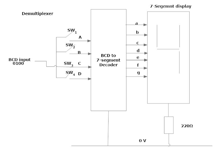
In practice current limiting resistors of about 150Ω to 220Ω would be connected in series between the decoder/driver chip and each LED display segment to limit the maximum current flow. There are different display decoders and drivers available for the different types of available displays, either LED or LCD. For example, the 74LS48 for common-cathode LED types, the 74LS47 for common-anode LED types, or the CMOS CD4543 for liquid crystal display (LCD) types. Liquid crystal displays (LCD’s) have one major advantage over similar LED types in that they consume much less power and nowadays, both LCD and LED displays are combined together to form larger Dot-Matrix Alphanumeric type displays which can show letters and characters as well as numbers in standard Red or Tri-colour outputs.
We used the following components for this experiment-
After Starting the experiment first click on the Components button to get component list. Now you can Drag and Drop any component in the circuit designing area. To make connection between components, just click on the Blue bubble of any components and Drag it to another Blue bubble of the same or any other components. To delete connection or to remove any component use Double click on that component or connection.
After connenting all the required components,click on the Start button and you will get a new start window, where you can give the inputs. After this,you click the run button and finally the outputs are shown.