Battery Test Bed Development
Development of an environment controlled battery test chamber
About
The main objective of this experiment is to develop an environmentally controlled chamber in order to be used for testing cylindrical/pouch/prismatic cells. A key design requirement is that the cell test chamber should be able to maintain an error accuracy within -1°C to +1°C of the desired temperature and ±2% error accuracy for desired humidity level, since a small change in temperature or humidity levels would significantly affect the test results of the battery cell. Since the temperature of the lab is not constant in which the testing is being done, it is necessary to obtain control over temperature to get accurate results of the performance of cell. In addition, the temperature and humidity control system should be able to maintain the desired levels of temperature within our test temperature range (-20°C to 80°C) and humidity within our test humidity range (30% to 80% RH) inside the test chamber without fail for the entire test duration which are usually quite long. Before the cell is ready for commercial use, a rigorous and thorough testing of the cell under various temperature and Humidity conditions is needed for long time to understand the battery performance and behavior and to have an idea about the life expectancy of the battery.
Technical description of cell test bed development
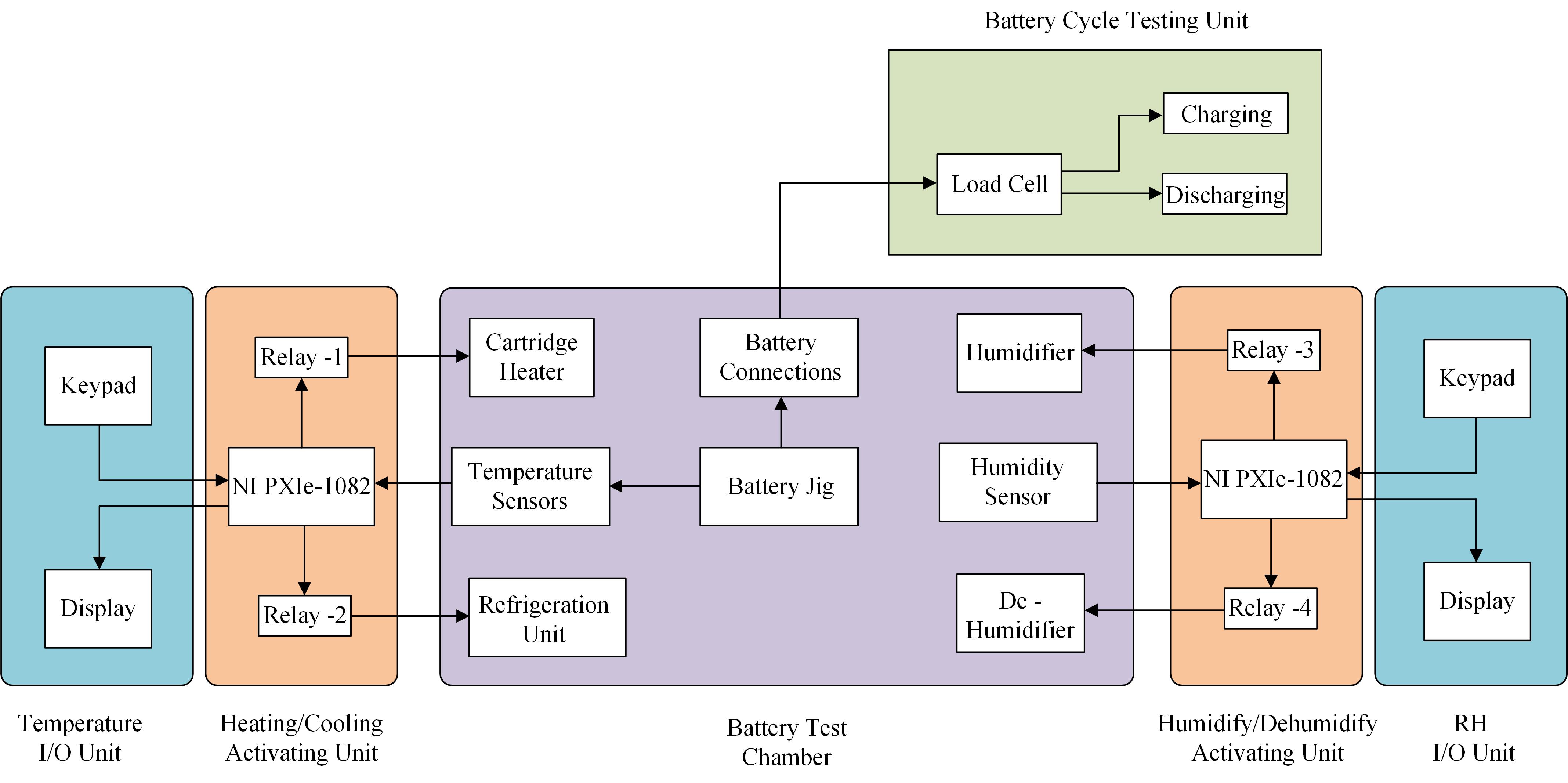
Fig.1: Functional block diagram for test-bed development
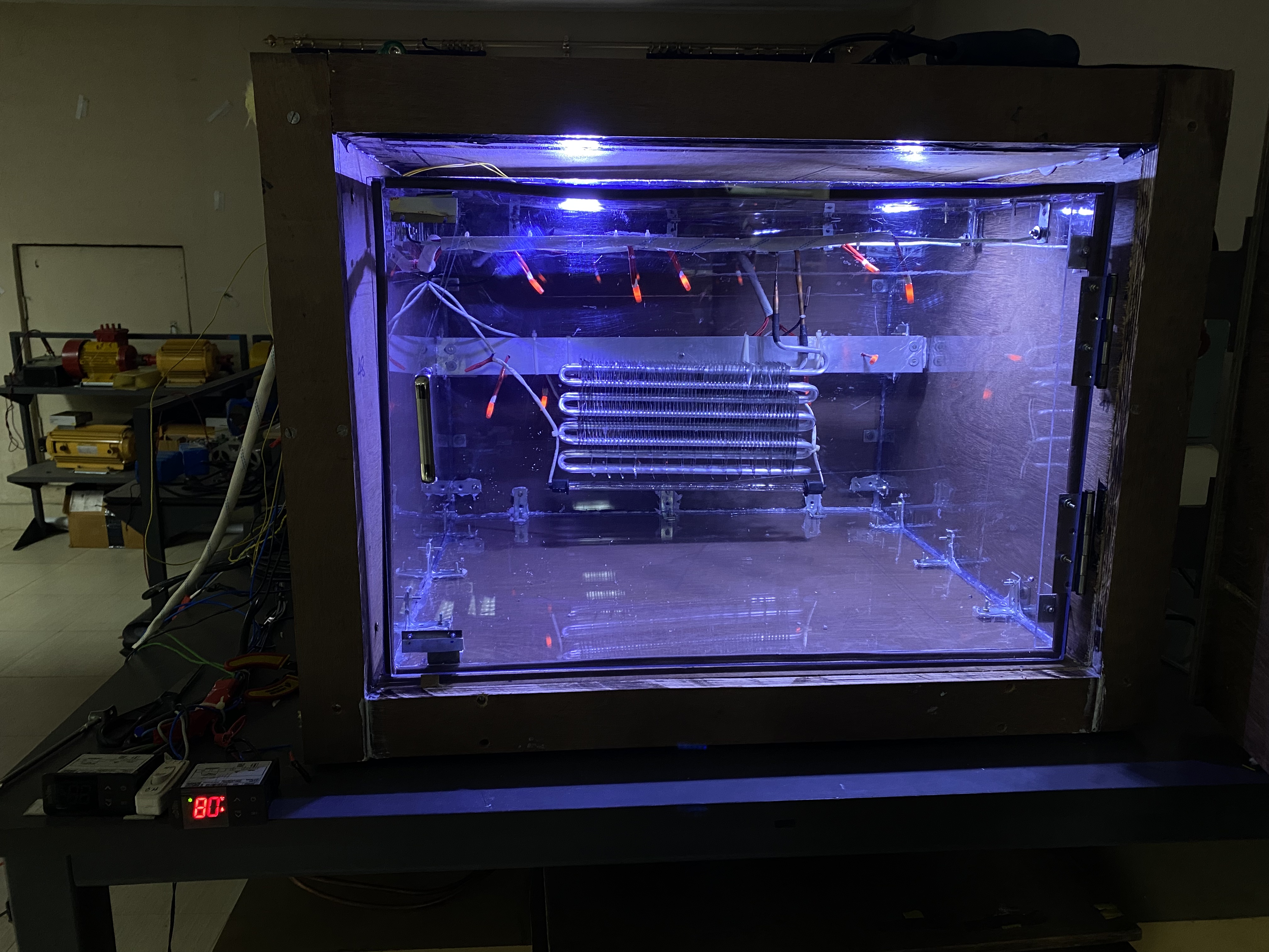
Fig 2.: Completed actual test bed hardware
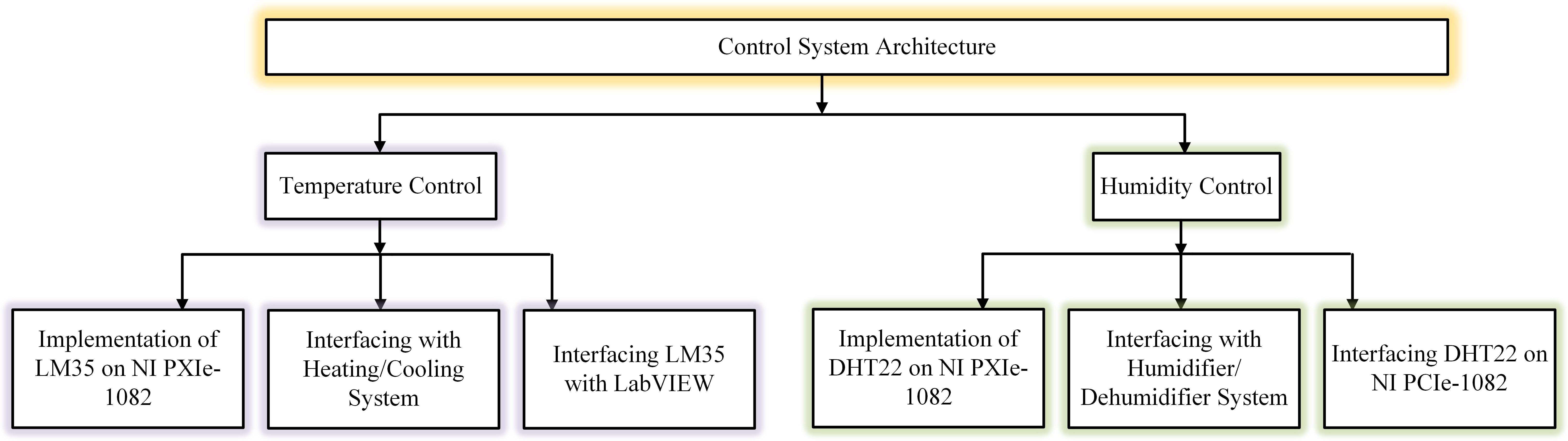
Fig. 3: Functionalities of control system architecture
Temperature sensing and control
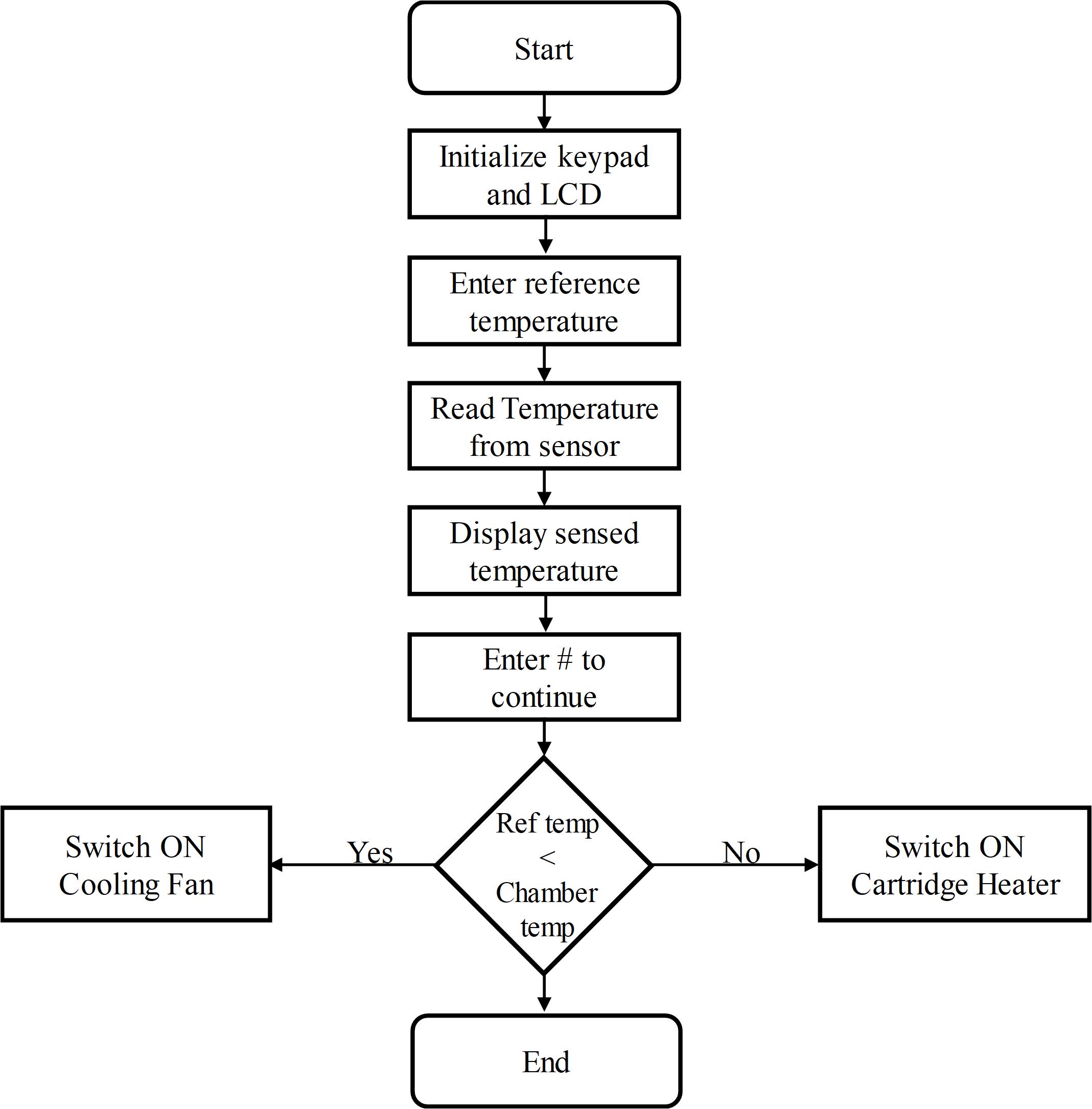
Fig. 4: Flowchart for temperature sensing and control unit
Sensing unit
Temperature sensing is done using LM35
Specifications of LM35:
Range: -55°C to 150°C
Current drawn from source: 60μA
Linear Scale factor of 10mV/°C
Accuracy: +/-0.5°C (at 25°C)
Output Voltage: 4V to 30V
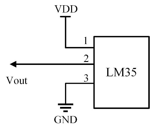
Fig.5: LM-35 sensor pin diagram
Data obtained from sensor is an analog voltage which is given to the analog pins of the NI PXIe-1082 Microcontroller. This voltage is linearly dependent on the measured voltage. So, information about respective ambient temperature can be easily extracted from it.
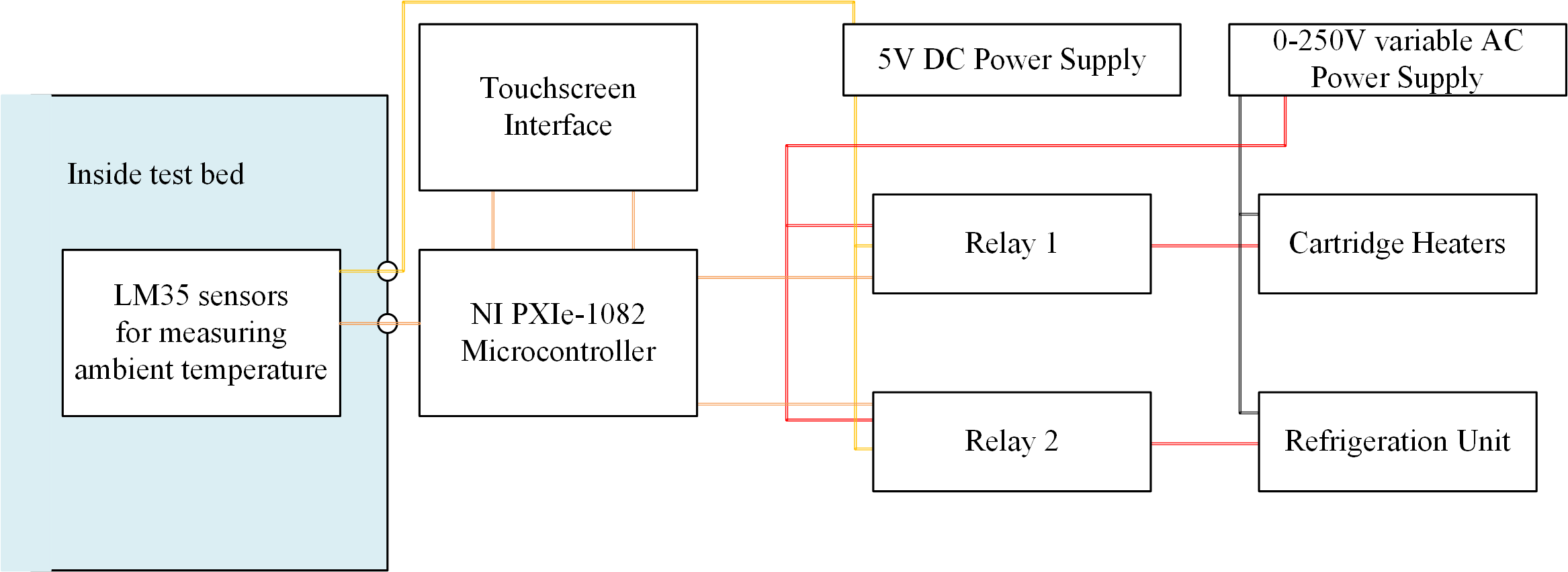
Fig. 6: Circuit diagram of temperature control Unit
Heating/Cooling unit
Heater element:
12V, 40W, Ceramic cartridge type
Switched ON/OFF, controlled by BJT
Cooling system:
Refrigeration system utilizing 12V DC, evaporator with forced air cooling, condenser, capillary tube
Switched ON/OFF, controlled by BJT
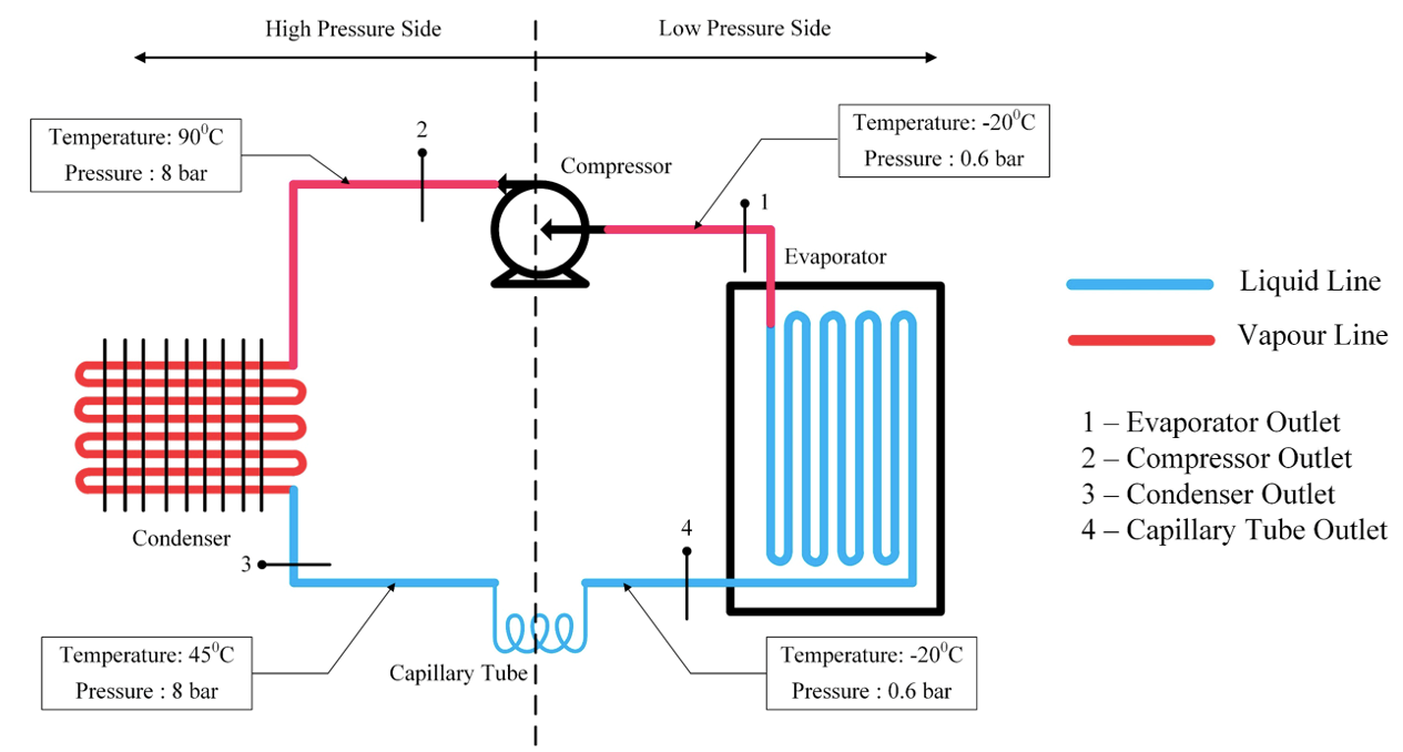
Fig.7: Schematic illustration and components layout of the refrigeration system
Humidity Sensing and Control
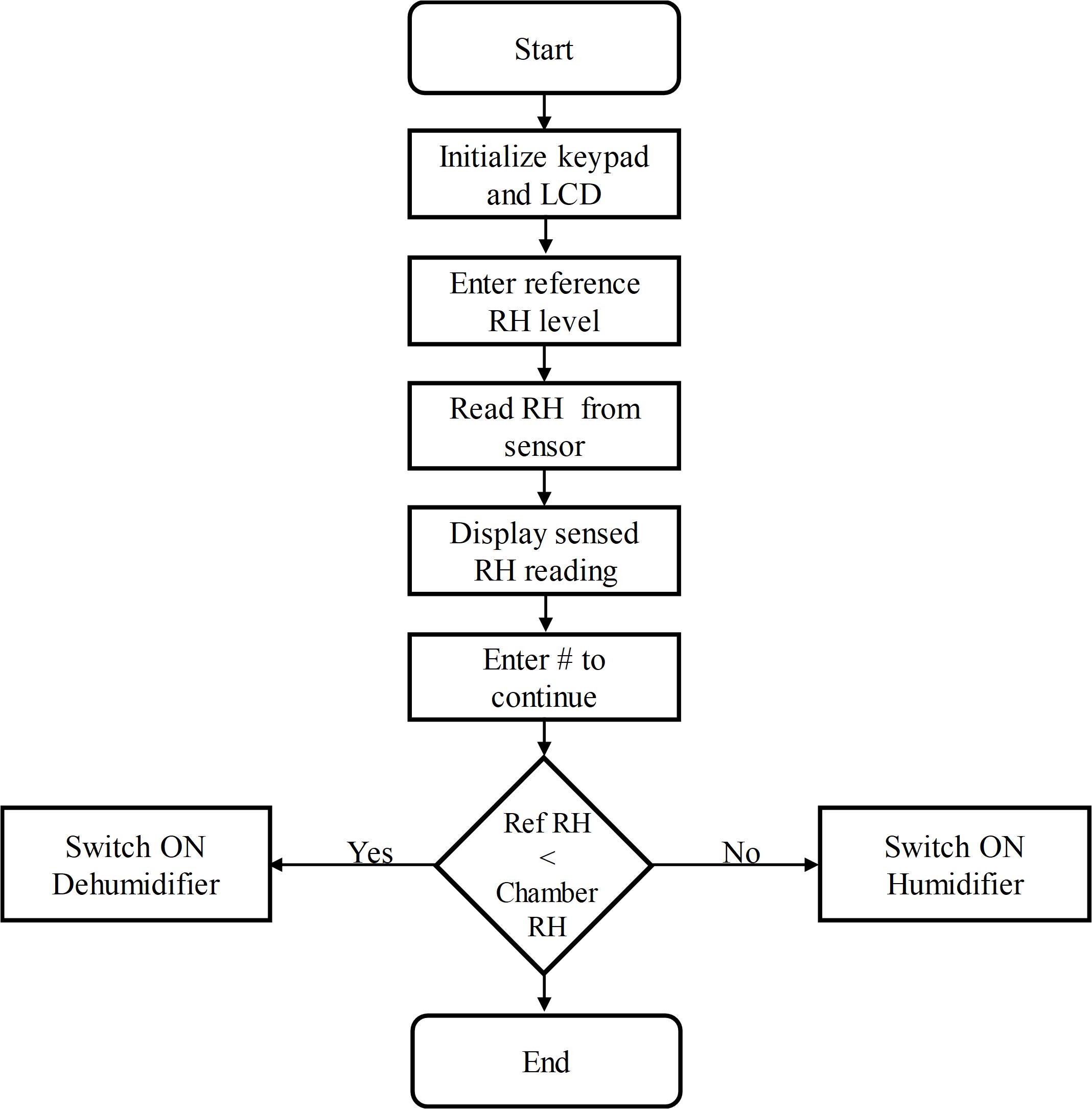
Fig. 8: Flowchart for humidity sensing and control unit
Sensing Unit
Humidity sensing is done using DHT22 humidity sensor
Specifications of DHT22:
- Power supply: 3.3V – 6V DC
- Output signal: single-bus
- Sensing element: polymer humidity capacitor & DS18B20
- Measuring range: humidity 0-100% RH / temperature -40°C – 125°C
- Accuracy: humidity ±2% / temperature ±0.2°C
- Sensing period: ~2s
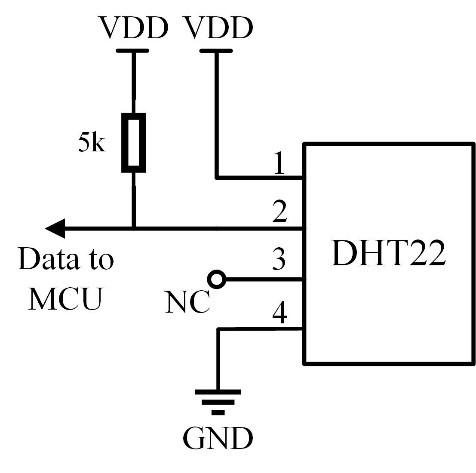
Fig. 9: DHT22 sensor pin diagram
Data obtained from sensor is given to the analog pin of the microcontroller. This voltage is linearly dependent on the measured humidity. So, information about respective humidity of the chamber can be easily extracted from it
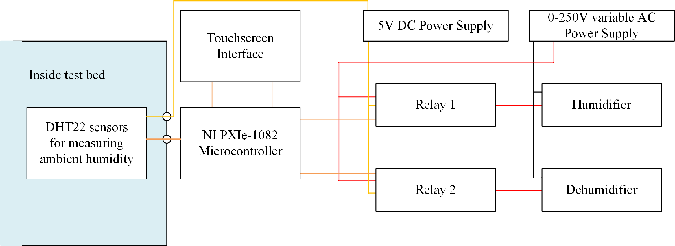
Fig. 10: Circuit diagram of humidity control unit
Humidifying/Dehumidifying unit
Humidifier:
12V, 20W - Air Humidifier (Portable)
Switched ON/OFF
Dehumidifier:
12V, 150ml, Dehumidifier
Switched ON/OFF
Specifications and ratings are illustrated in table-1 of User Manual (See below)
Experimental Procedure
From table-1 in specification manual (see below) section, buy all the components, parts and materials required for test chamber development.
Heating/Cooling unit assembly
- A three layered insulated box (having dimensions as 81(l) x 75(b) x 75(h)) consisting of one glasswool layer sandwiched between two wooden plywood layers is constructed.
- An acrylic box of dimension 65(l) x 60(b) x 45(h) cm is made (with internal volume ~175 ltr) and a cell holder is placed in the middle.
- The acrylic box is inserted inside the wooden box for better insulation and humidity/temperature stability
- Two 1/4 inch NPT port holes are made at the back of the box as shown in Fig.7.5 to install the copper pipes for condenser. The condenser arrangement must be inserted properly into the internal space. Use super 7 hybrifix sealant to insulate around the port orifices.
- Make three 1/4 inch NPT port hole at the right wall of the box for battery terminal port, sensor port and heating/cooling terminal Ports respectively. Use super 7 hybrifix sealant to insulate around the heatsink.
- A condensate box is prepared for draining out the condensed water particles from the test bed as shown in Fig 7.4.
- LM35 sensors are inserted inside the chamber.
- 9 numbers of 12V, 40W ceramic cartridge heater are inserted into the test chamber and it is made sure the output terminals are projected out from the test bench surface as shown in Fig 7.1.
- Rubber gaskets are fitted around the inner surface of the acrylic as well as door of the chamber for better insulation.
Electronics Unit Assembly
- Cooling unit is connected to 5V low-level relay (R1)
- Nine 12V, 40W Ceramic Cartridge Heaters are all connected in series so as to keep the current input to minimum. This enables us to use thin wires for connection. As per the ratings, 108V DC is applied across all the nine heaters in series through a relay. The relay is again a low-level one and operates at 5V DC.(R2)
- Cell voltage measurement is done through a 16bit ADC for greater precision and to provide isolation.
- NI PXIe-1082 is programmed using Python language. It can then be interfaced with LabVIEW on a PC.
- Connections of all temperature and humidity sensors are made inside the test chamber
Drawings
Note: All dimensions mentioned in the following drawings are in 'cm' unless stated otherwise
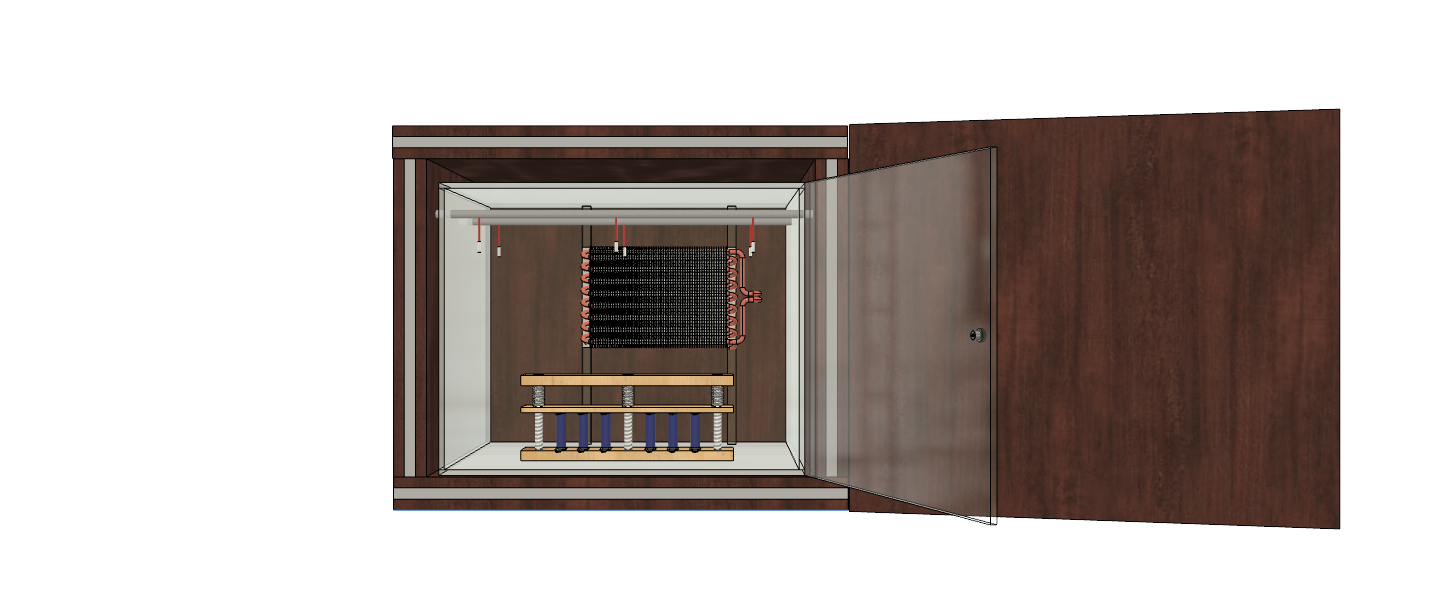
Fig. 11: Acrylic Hinged, Front-Load Cell Test Chamber Drawing – Front view
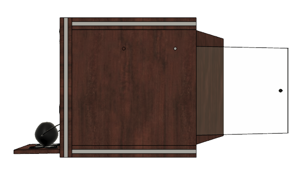
Fig. 12: Acrylic Hinged, Front-Load Humidification Unit Drawing – Left view
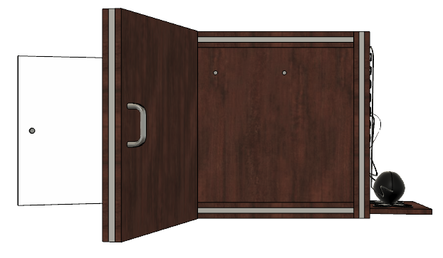
Fig. 13: Acrylic Hinged, Front-Load Humidification Unit Drawing – Right view
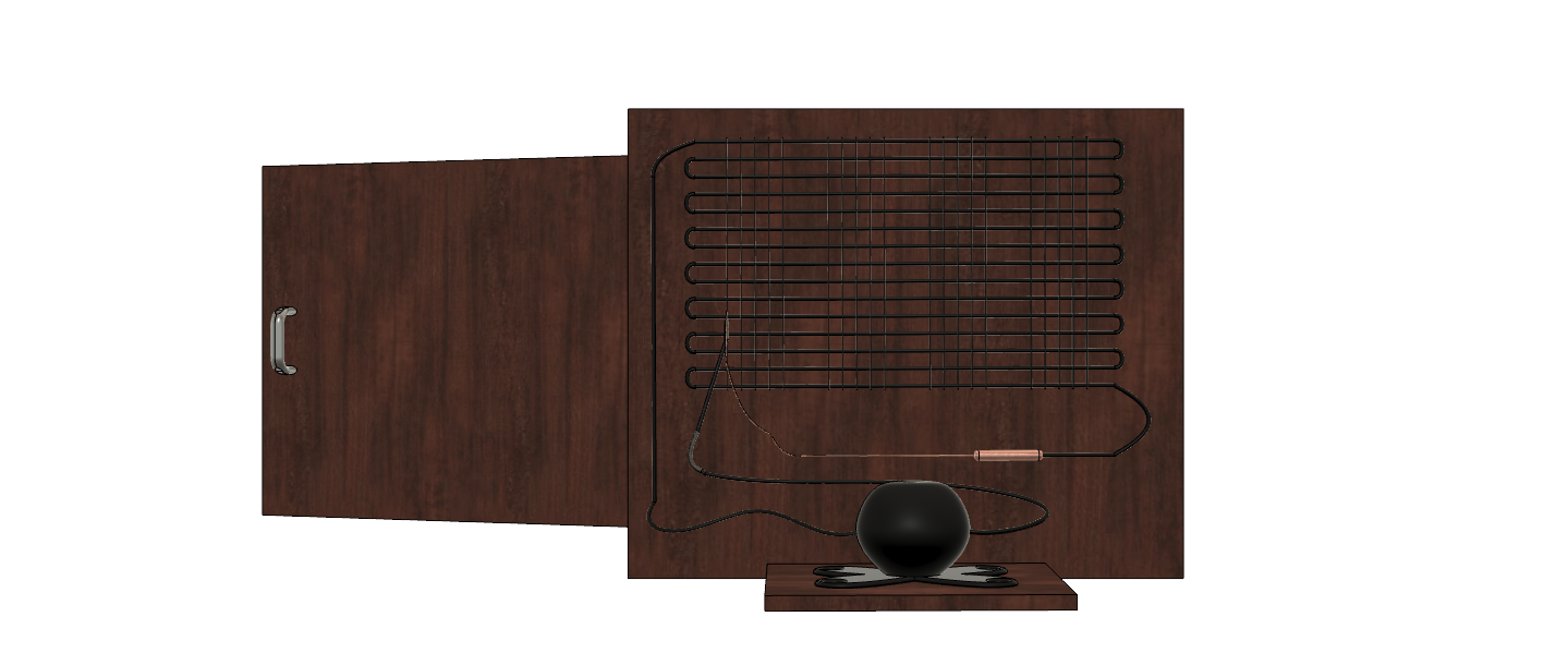
Fig. 14: Acrylic Hinged, Front-Load Humidification Unit Drawing – Rear view
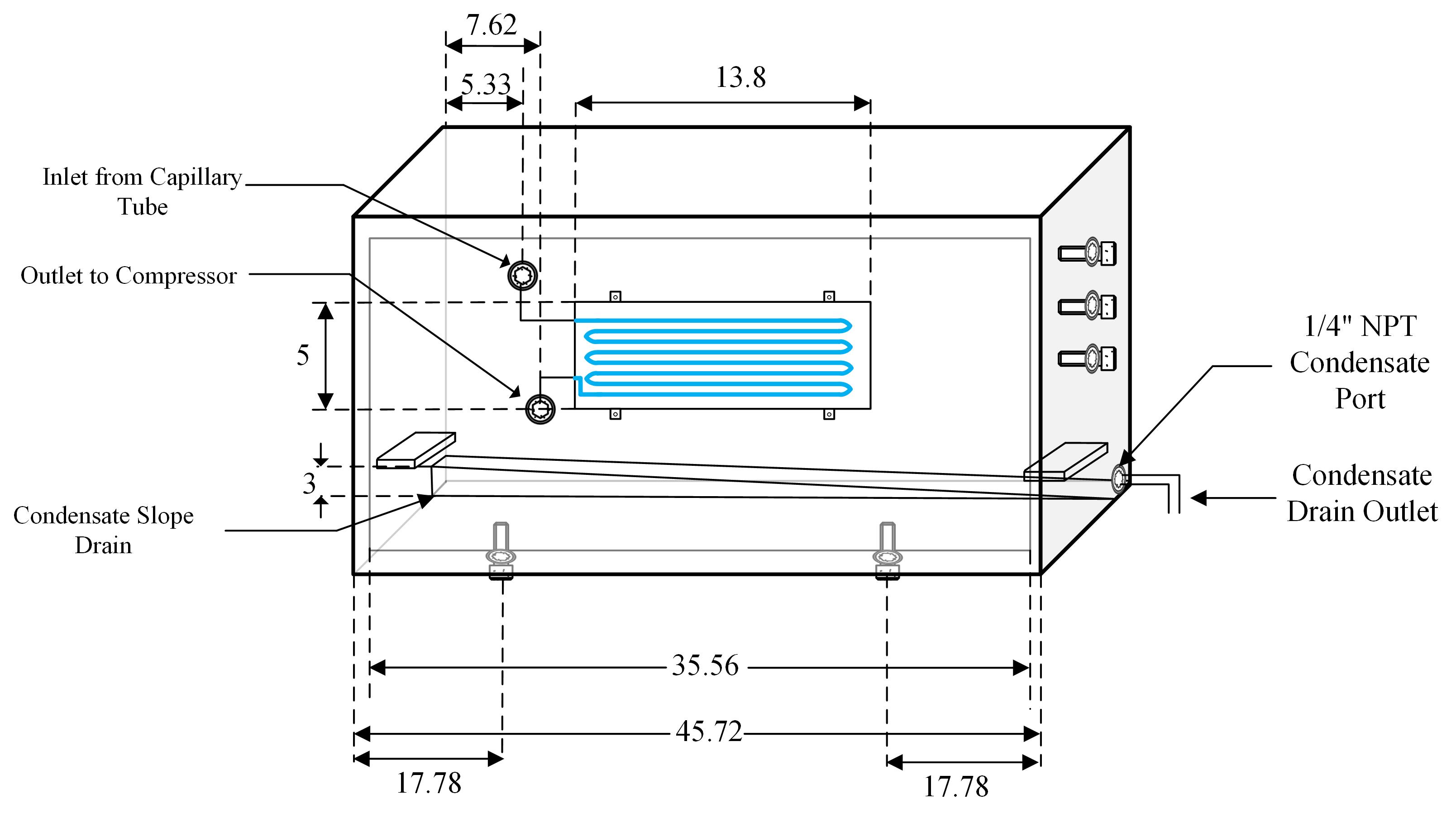
Fig. 15: Acrylic Hinged Front Load Chamber Drawing (Refrigeration Unit)
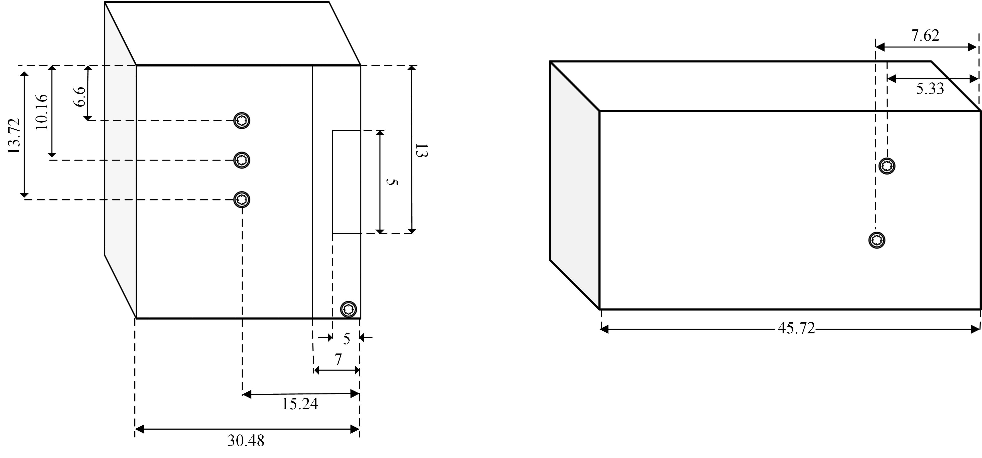
Fig. 16: Acrylic Hinged Front Load Chamber Drawing (Refrigeration Unit)
Fig. 17: Acrylic Hinged Front Load Chamber with Refrigeration Unit
Fig.7.6: Image source for Refrigeration Unit shown
Fig. 18: 1/4 Inch NPT Thread Body Dimensions
